By Angelica J
For my project, I wanted to use the Arduino to demonstrate the refraction of light. To do this I used a combination of the Photocell and LED lights in the available colors (red, yellow, green, and blue). I also want to add some pizzazz to this by adding a buzzer that would play “Over the Rainbow” from the film “Wizard of Oz” to hit the point home.
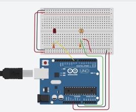
The first thing I had to do was to learn how to actually use the Photocell. I used these two tutorials:
- https://www.instructables.com/Light-Sensor-Photoresistor-Arduino-Tinkercad/
- https://www.instructables.com/How-to-use-a-photoresistor-or-photocell-Arduino-Tu/
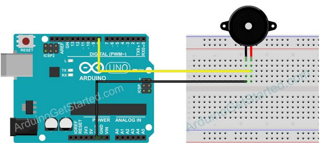
to help me understand how to use the Photocell. I followed the 1st link’s diagram (Figure 1) and the 2nd link’s code to create my own test (Figure 2).

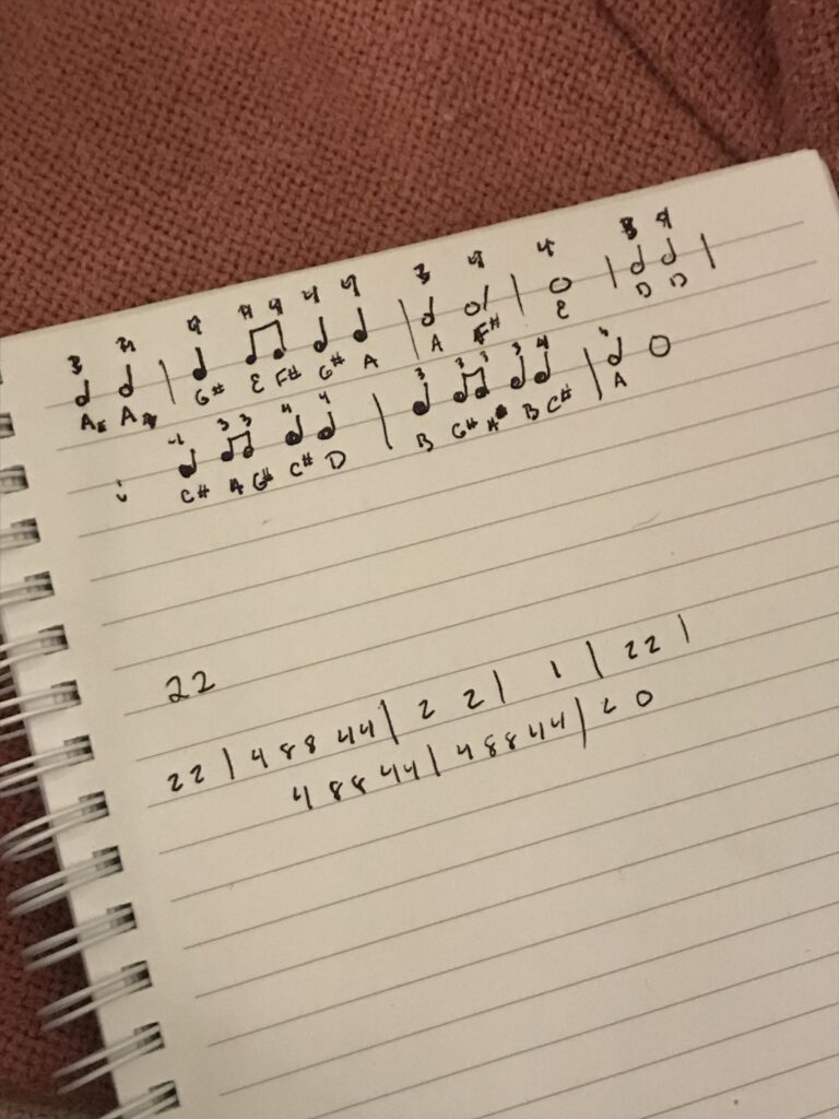
After I familiarized myself with the Photocell. I wanted to work on the buzzer part of the project. The first thing I tackled was the music element. I already had a copy of “Over the Rainbow”, so all I had to do was write it out to easily convert to code for the Pitches library (this can be seen in Figure 4). With the first 8 measures of the song chosen, I wrote out the notes names and the duration of the notes (whole=1, half=2, quarter=4, & eight=8).
After some testing, I realized that I couldn’t use the Pitches library for this project because I could use the buzzer and the LED light at the same time. After some digging I used these links:
- https://arduinogetstarted.com/tutorials/arduino-buzzer-library
- https://arduinogetstarted.com/library/buzzer/example/arduino-melody-repeat
to use the EZBuzzer library. It is similar to the pitches library but instead of using a for loop to play the array of notes, it calls a function to do it instead.
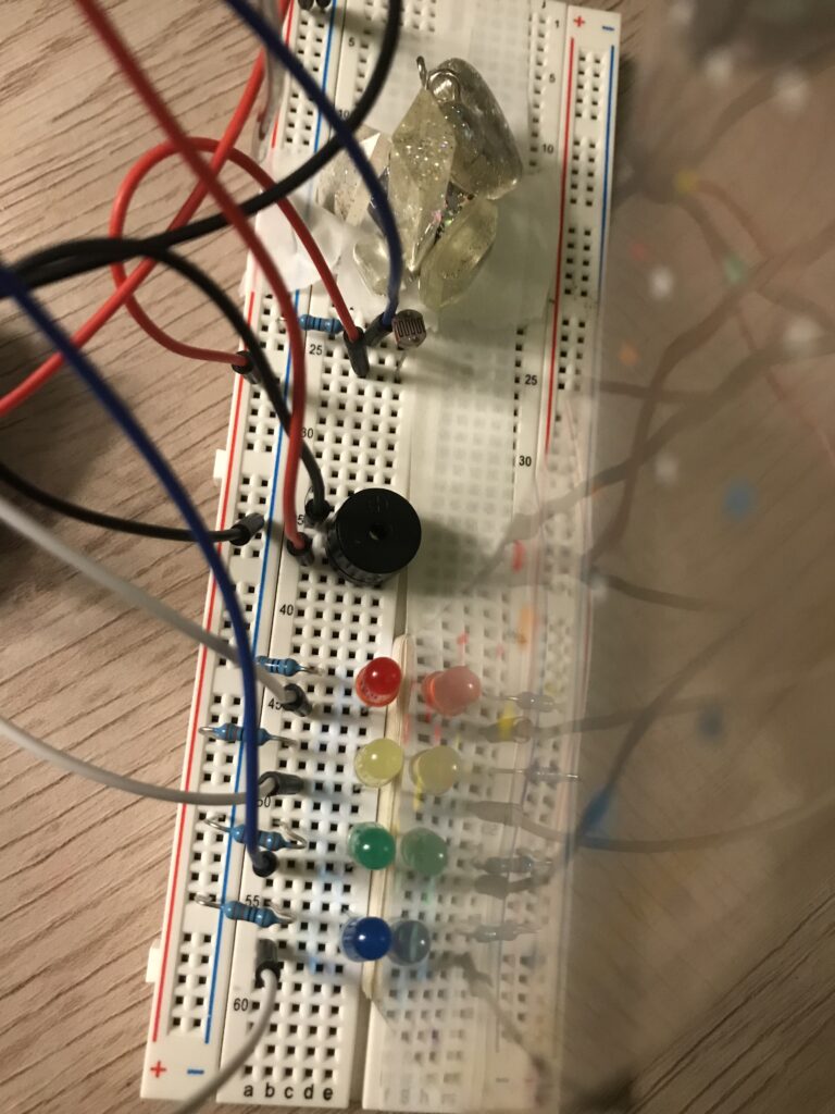
I then started to combine all of the elements together to see if it actually work together, as seen in figure 5.
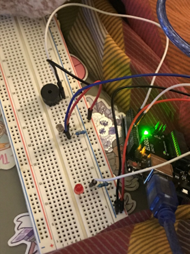
Below you can see the end result of my several tests for this project. I ended up using 4 LEDs, wired the same way as figure 1. There also is a video of my project working. As you shine the light on the “crystal” (aka the Photocell), the white light should then be “refracted” into the rainbow (aka the LEDs). The song plays as confirmation that a rainbow is in fact there.
Here’s my code:
/* Attention Project: Light Refracting*/

#include <ezBuzzer.h>
//Constants
const int pResistor = A0; // Photoresistor at Arduino analog pin A0
const int ledPinR=9;       // Led pin at Arduino pin 9
const int ledPinY=10;
const int ledPinG=11;
const int ledPinB=12;
const int buzzerPin=8;    //Buzzer Pin set to 8

//Variables
int value;				  // Store value from photoresistor (0-1023)
ezBuzzer buzzer(buzzerPin); // create ezBuzzer object that attach to a pin;
// notes in the melody:
int melody[] = {
  NOTE_A3, NOTE_A4,
  NOTE_GS4, NOTE_E4,NOTE_FS4,NOTE_GS4,NOTE_A4,
  NOTE_A3,NOTE_FS4,
  NOTE_E4,
  NOTE_D3,NOTE_D4,NOTE_CS4,NOTE_A3,NOTE_GS3,
  NOTE_CS4,NOTE_D4,NOTE_B3,NOTE_GS3,NOTE_A3,
  NOTE_B3,NOTE_CS4,
  NOTE_A3,0
};
// note durations: 4 = quarter note, 8 = eighth note, etc.:
int noteDurations[] = {
  2,2,
  4,8,8,4,4,
  2,2,
  1,
  2,2,
  4,8,8,4,4,
  4,8,8,4,4,
  2,0
};

void setup()
{
  Serial.begin(9600);
  pinMode(ledPinR, OUTPUT);  // Set lepPin - 9 pin as an output
  pinMode(ledPinY, OUTPUT);  // Set lepPin - 9 pin as an output
  pinMode(ledPinG, OUTPUT);  // Set lepPin - 9 pin as an output
  pinMode(ledPinB, OUTPUT);  // Set lepPin - 9 pin as an output
  pinMode(pResistor, INPUT);// Set pResistor - A0 pin as an input (optional)
}

void loop()
{
  buzzer.loop();
  value = analogRead(pResistor);

  //You can change value "25"
  if (value > 40)
  {
    digitalWrite(ledPinR, HIGH);  //Turn led on
    digitalWrite(ledPinY, HIGH);  //Turn led on
    digitalWrite(ledPinG, HIGH);  //Turn led on
    digitalWrite(ledPinB, HIGH);  //Turn led on
    if (buzzer.getState() == BUZZER_IDLE)
    {
      int size = sizeof(noteDurations) / sizeof(int);
      buzzer.playMelody(melody, noteDurations, size);   //playing
    }
  }
  else
  {
    digitalWrite(ledPinR, LOW); //Turn led off
    digitalWrite(ledPinY, LOW); //Turn led off
    digitalWrite(ledPinG, LOW); //Turn led off
    digitalWrite(ledPinB, LOW); //Turn led off
    if (buzzer.getState() != BUZZER_IDLE)
    {
      buzzer.stop();    //stop
    }
  }
  delay(10); //Small delay to stop buzzer from glitching
Leave a Reply