KY-027 Magic Light Cup Module
Sensor Description
The KY-027 Magic Light Cup module is a set of two boards. Each one has a LED and a mercury tilt switch. Using PWM to drive the LEDs on each module, you can achieve the effect of light being “magically” transferred from one module to the other when tilting them, similar to pouring water from one cup to the other, hence the name.
In other words, the pair can be used as a tilt sensor. I am thinking about creating a fun game out of it. Tilt the board until reach a brightness amount that is between 2 numbers, or the most difficult one, precisely on 1 number (can be adjusted through code) to stop the buzz.
If playing it through watching the brightness of the LED light from the Light Cup Module is too difficult, there will be brightness readings on the Serial Monitor.
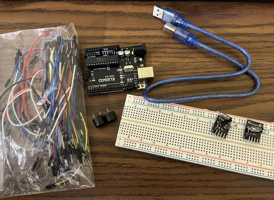
Requirements
- Arduino UNO
- Breadboard Jumper Wire
- KY-027 Magic Light Cup Module
- Passive Buzzer
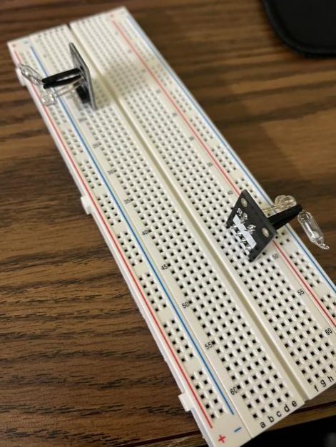
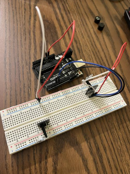
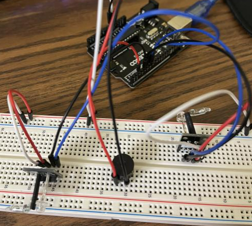
Step 1: Plugin the Magic Light Cup Module pair
Step 2: Connect GND Pin with GND rail & VCC Pin of Light Cup Module with 5V rail of Breadboard
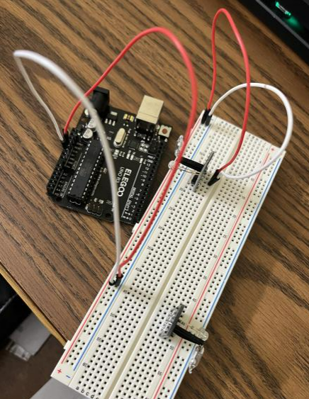
Step 3: Connect Signal Pin with Digital Pin-7 of Arduino Uno
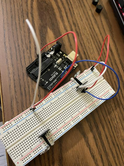
Step 4: Connect LED Pin of Light Cup Module with Digital Pin-5 of Arduino Uno
Step 5: Repeat step 2 on the breadboard for the 2nd Light Cup Module
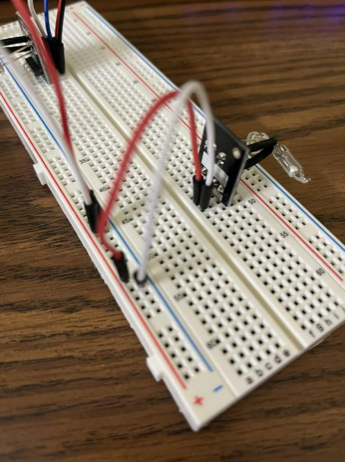
Step 6: Connect Signal Pin with Digital Pin-4 of Arduino Uno
Step 7: Connect LED Pin of Light Cup Module with Digital Pin-6 of Arduino Uno
Code: test with what we have so far
int ledPinA = 5;
int switchPinA = 7;
int switchStateA = 0;
int ledPinB = 6;
int switchPinB = 4;
int switchStateB = 0;
int brightness = 0;
void setup()
{
pinMode(ledPinA, OUTPUT);
pinMode(ledPinB, OUTPUT);
pinMode(switchPinA, INPUT);
pinMode(switchPinB, INPUT);
}
void loop()
{
switchStateA = digitalRead(switchPinA);
if (switchStateA == HIGH && brightness != 255)
{
brightness ++;
}
switchStateB = digitalRead(switchPinB);
if (switchStateB == HIGH && brightness != 0)
{
brightness –;
}
analogWrite(ledPinA, brightness); // A slow fade out
analogWrite(ledPinB, 255 – brightness); // B slow bright up
delay(20);
}
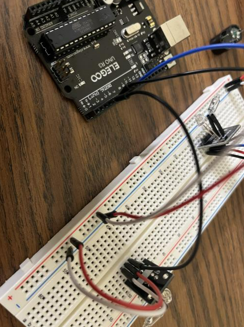
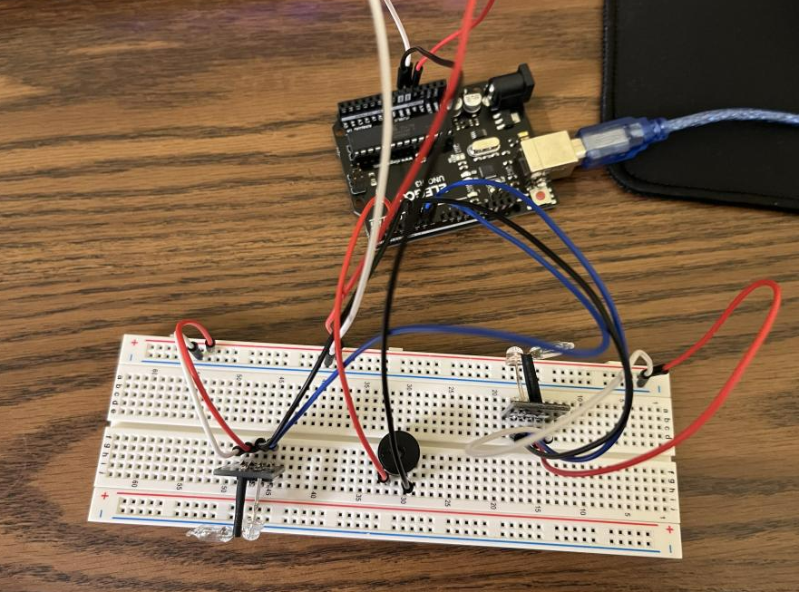
Step 8: Plug the passive buzzers in, connect the Buzzer (+) to Arduino Pin 2 and the Buzzer (-) to Arduino Pin GND
Step 9: When the brightness is not between 125 and 130, buzz
Code
int ledPinA = 5;
int switchPinA = 7;
int switchStateA = 0;
int ledPinB = 6;
int switchPinB = 4;
int switchStateB = 0;
int brightness = 0;
int buzzerPin = 2;
void setup()
{
Serial.begin (9600);
pinMode(ledPinA, OUTPUT);
pinMode(ledPinB, OUTPUT);
pinMode(switchPinA, INPUT);
pinMode(switchPinB, INPUT);
pinMode(buzzerPin, OUTPUT);
}
void loop()
{
if (brightness <= 125 || brightness >= 130) {
tone(buzzerPin, 100);
}
else {
noTone(buzzerPin);
}
switchStateA = digitalRead(switchPinA);
if (switchStateA == HIGH && brightness != 255)
{
brightness ++;
}
switchStateB = digitalRead(switchPinB);
if (switchStateB == HIGH && brightness != 0)
{
brightness –;
}
Serial.println(brightness);
analogWrite(ledPinA, brightness); // A slow fade out
analogWrite(ledPinB, 255 – brightness); // B slow bright up
delay(20);
}
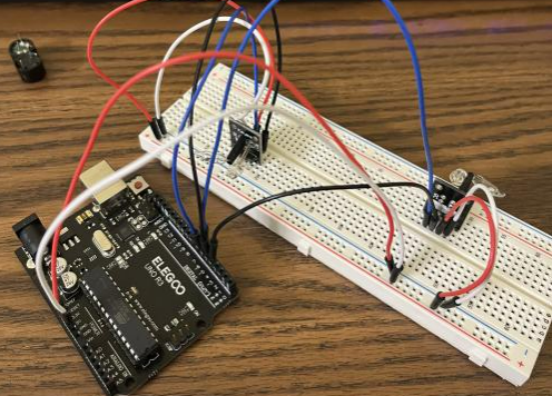
Demo
Serial monitor reading
Conclusion
In the beginning, I followed this tutorial to gather all the components and the code that I need to build the project. I also watched this YouTube tutorial about wiring. After I finished the wiring by following the YouTube tutorial, I adjusted the code from the ArduinoModules tutorial to set up the code for the corresponding input pins’ inputs and outputs correctly. Moreover, added tones to the buzzer and the game mechanics that detects whether it should buzz or not.
In general, the project works well. However, the brightness of the LED light of the Light Cup Module might not be obvious enough to observe with bare eyes. Therefore, reading the brightness value from the Serial Monitor is kind of necessary when playing with it.
Always keep in mind that testing is important in each phase/step before you move on, otherwise, it will only get more and more difficult for you to debug or figure out what is wrong.
Leave a Reply