For my random sensor project, I received this sensor:

It turned out to be a KY-002 Vibration Sensor. I could figure that out because there’s a tiny spring inside the cylinder that seemed to vibrate easily, leading me to guess it was a vibration sensor. It’s basically a standard button, except instead of having to press down, the spring has to contact the outer cylinder to complete the circuit. At first I thought it would be an analog signal representing how strong it was vibrating, but no, it’s just a binary signal.
Here’s the recommended setup:
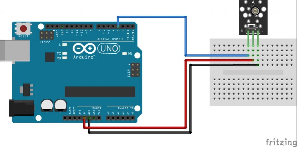
However
You don’t actually need the red wire if you set up your input pins correctly. If the sensor output is in port 3, you can set pinMode(3, INPUT_PULLUP); to add built-in resistor to the pin and avoid the extra wire to 5V.
As I was testing the sensor with a basic setup, I noticed how satisfying the interaction of tapping anywhere on the device to activate the sensor was, and it reminded me of another device, the Etch-a-Sketch. So, decided to make my own version, for which I could use another component I had been waiting for a chance to work with:
Dot Matrix
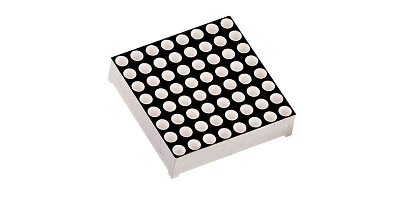
This is an 8×8 LED dot matrix. I’ve had one for years but never had a chance to use it until now.
Pros and Cons of Dot Matrix
Pros
- It looks cool
- You can draw pictures on it
Cons
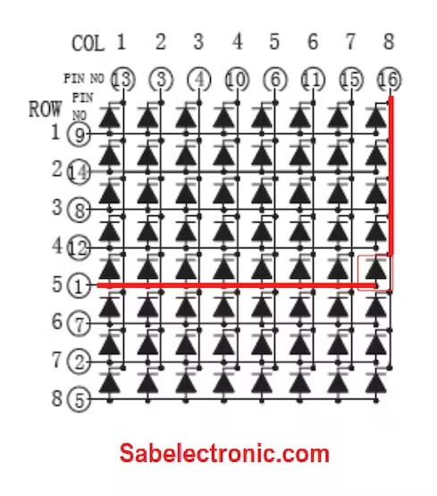
- It requires 16 pins
- They are in a completely random order
- They’re not even separated into rows and columns
- This design is the work of a madman
Despite the cons, “it looks cool” won out, so I decided to use it, along with the vibration sensor, to make:
The Etch-a-Sketchy
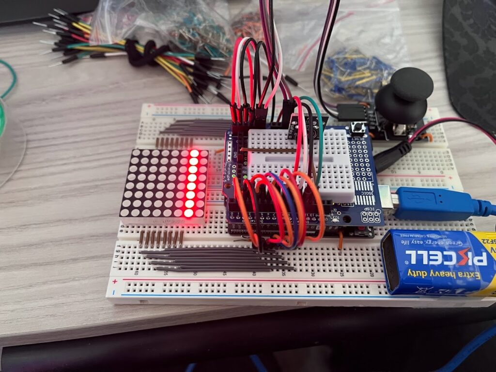
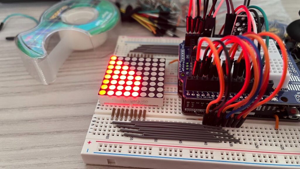
I made a digital Etch-a-Sketch using the dot matrix, the vibration sensor, a joystick module, and of course an Arduino.

The dot matrix comes with a microcontroller that attaches to the 16 pins and handles controlling the LEDs with only 3 output pins coming from the Arduino. However I couldn’t get it to work, so I just directly connected the 16 pins to the Arduino, and started by just testing lighting up one column at a time:
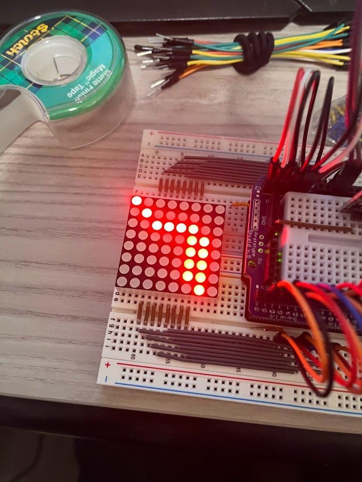
Because the dot matrix just lets you turn on individual columns and rows, it’s not possible to display more complex images all at once. Instead you have to do multiplexing! That’s where you turn each column on one at a time, so fast that it looks like they’re all on at once.
If you photograph multiplexing with a short enough exposure or a long enough delay, you can see that not all of the lights are actually on at once. But to the naked eye, this looks like a full staircase pattern!
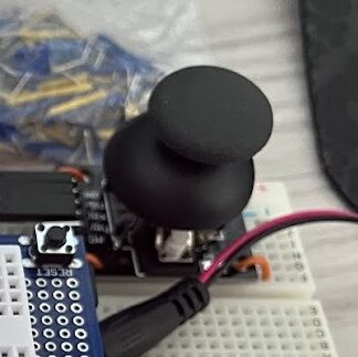
With the display working, I decided to set up a ‘pen’ next to control where you can draw on the screen. To do this, I attached a joystick module to the analog input ports, and added logic in my code to keep track of the pen’s position, move it when you move the joystick, and turn on the LED’s once you pass over them.
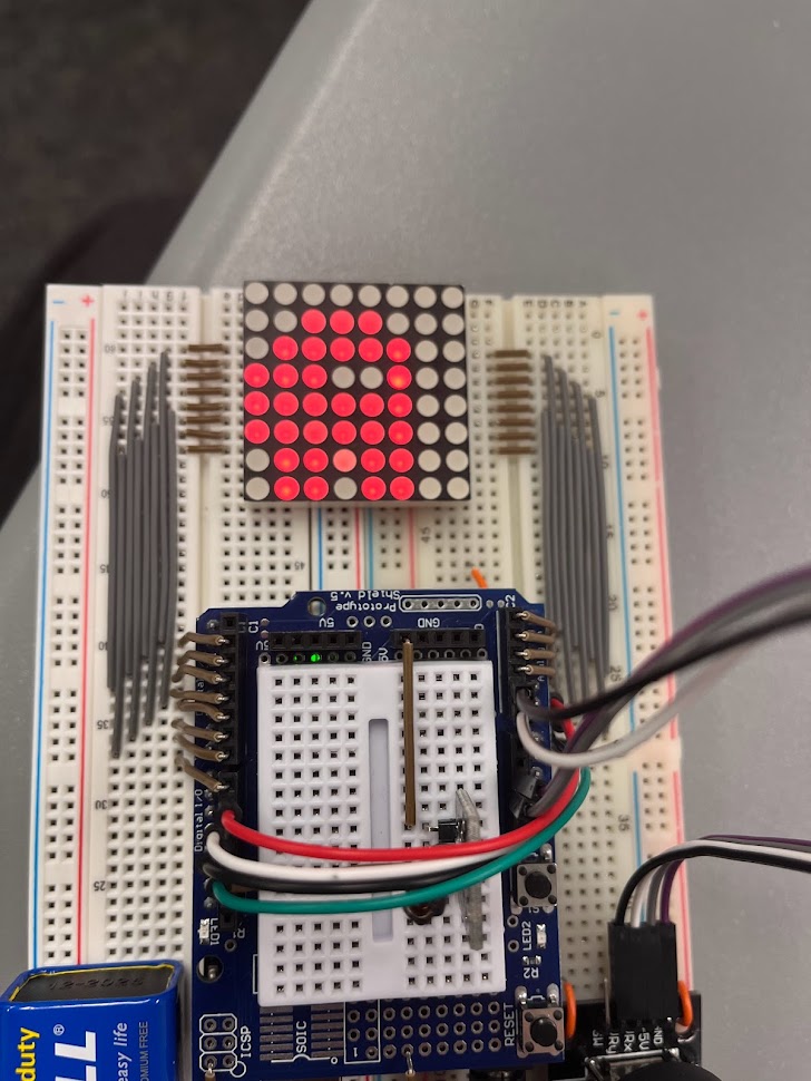
Finally I added the vibration sensor, and added new code to reset the LED’s when it’s triggered
And with that, the Etch-a-Sketchy is complete! The complete source code is available on my Github at https://github.com/MGPAlpha/lmc3818/blob/main/Sensor%20Project/Sensor%20Project.ino.
I also created a short video of the Etch-a-Sketchy, in the form of an infomercial:
Leave a Reply