My random sensor is a KY-036 human/metal touch sensor. It has 4 header pins. The D0 pin represents digital output, the positive (+) pin represents +5V, the G pin represents Ground, and the A0 pin represents analog output. The difference between analog output and digital output is that analog signals are continuous/time varying while digital signals are non-continuous/either ON or OFF. You will only receive a digital signal at set intervals. The A0 on the sensor is the direct measurement value of the sensor unit while the D0 releases a signal output if a touch is detected. The LED1(L1) part on the Ky-036 module shows that the power is on and the LED2(L2) part lights up when a touch is detected.
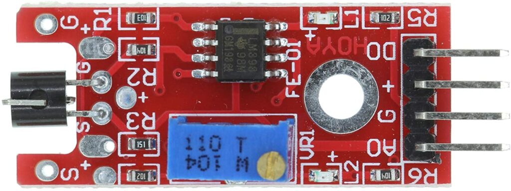
The Ky-036 module detects electric conductivity in our bodies as well as from objects that are electrically charged. If we touch the metal part of the sensor with our skin, the Arduino will detect a signal. The sensor unit (the black piece in the front of the Ky-036) measures the current environment and sends an analog signal to the amplifier. The signal is then amplified based on the sensitivity of the potentiometer (resistance), which can be adjusted by twisting the gold top, and then sent to A0. The comparator switches the D0 and the LED2 if the signal falls under a certain value. In my case, once the sensor is touched by a conducting body a switch is triggered, the Arduino detects the signal from the D0, and it signals for the LED on the breadboard to be turned on. Ky-036 modules are commonly used in electric devices such as mobile touch screens. This is the reason behind your touchscreen only operating when it has been touched by your fingers or something that is receiving electrical charge from your fingertips and unaffected otherwise when touched with other objects.
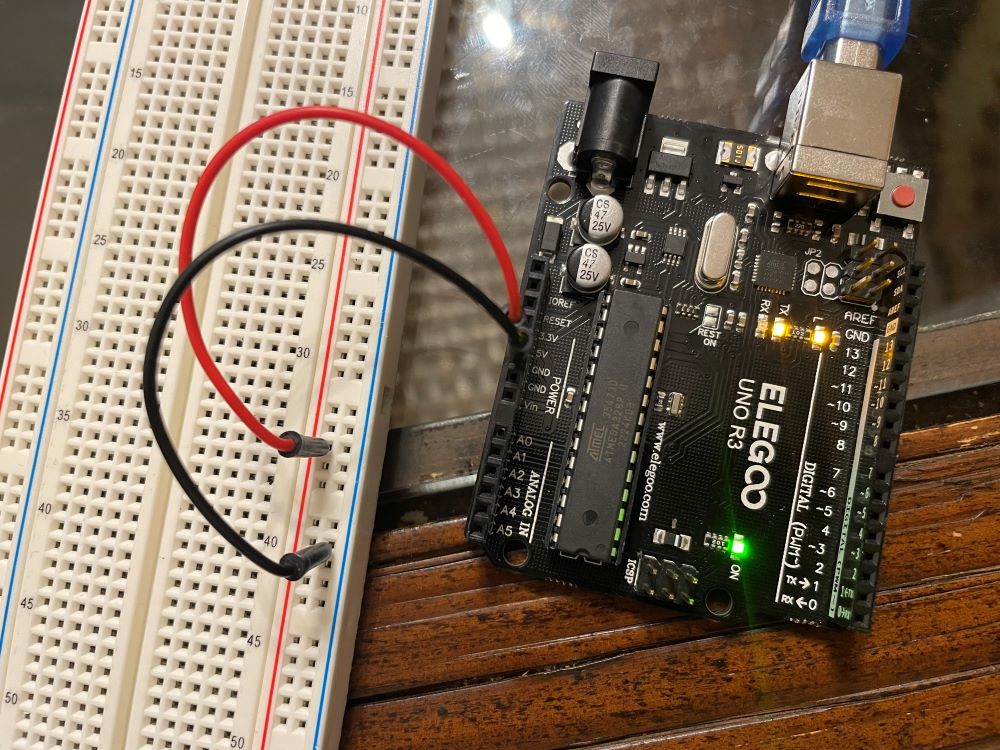
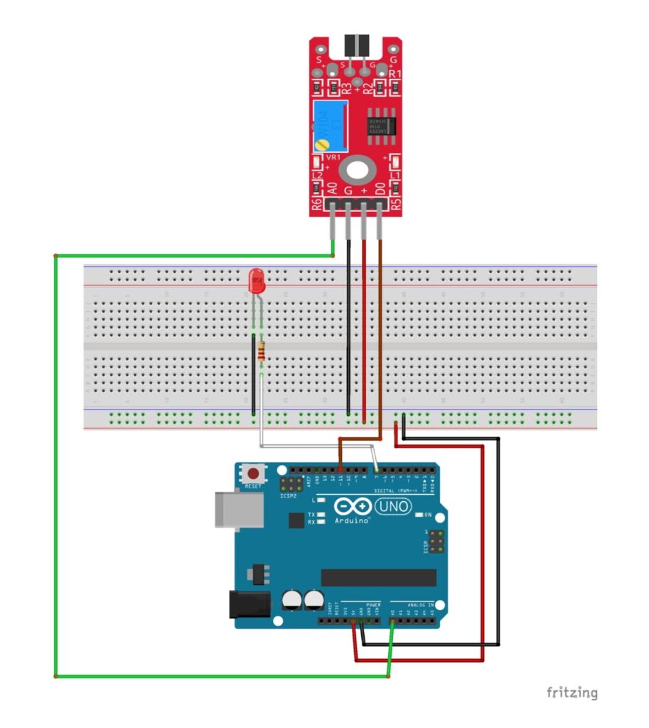
First, I connected the 5V pin to a + slot on the breadboard & then the GND pin to the – slot on the breadboard.
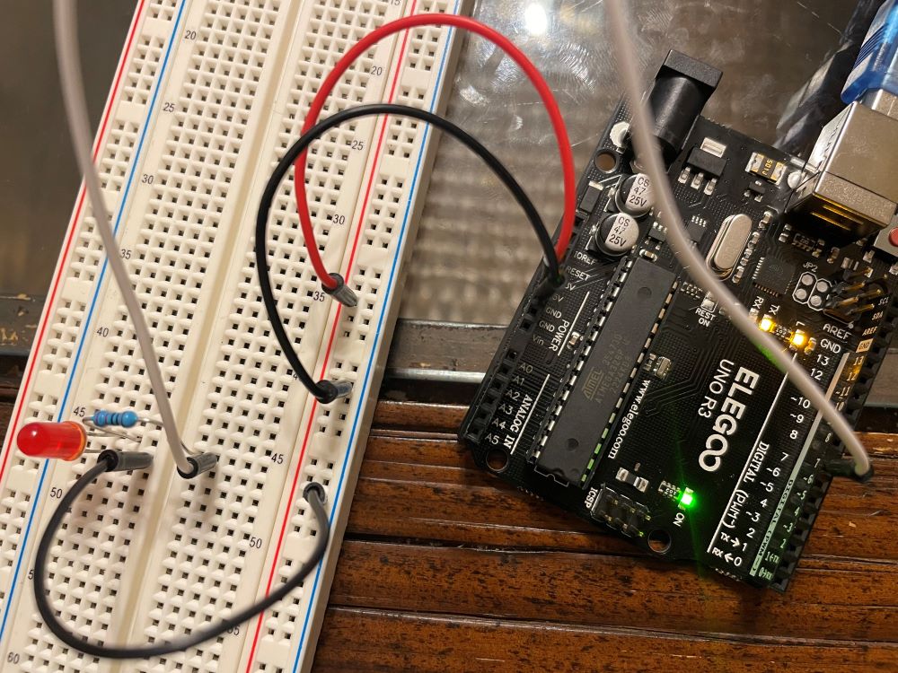
I then connected the LED to the Arduino. I connected the anode (+) of the LED to a 220 ohm resistor that’s connected to pin 7. The resistor protects the LED from being damaged by too much current. I then connected the cathode (-) of the LED to the ground of the breadboard.
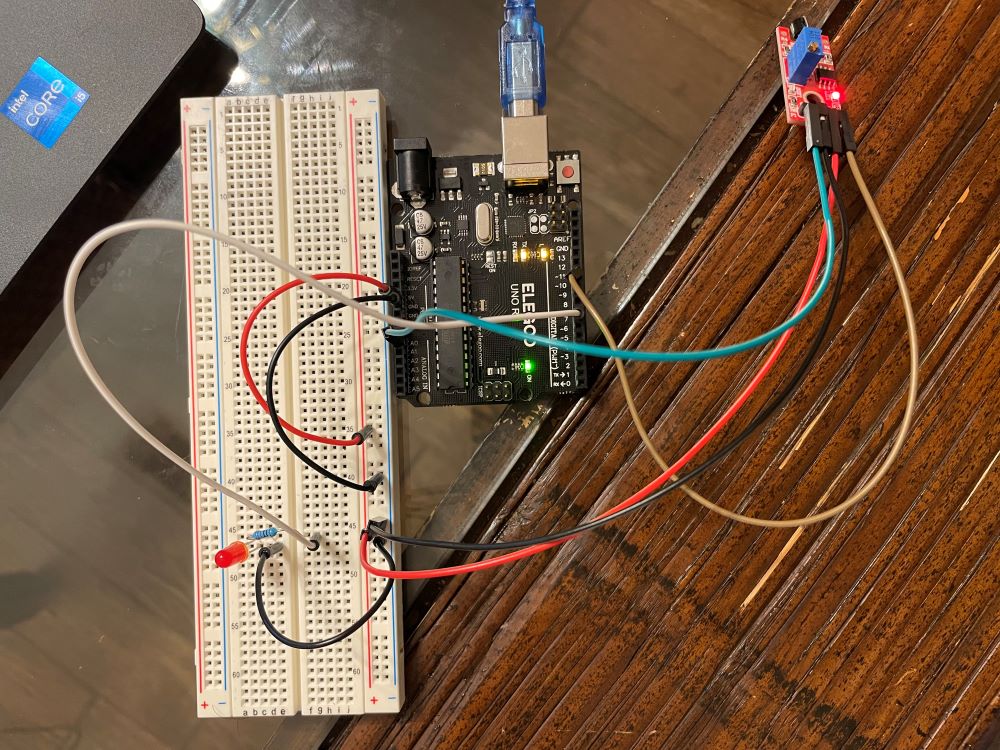
I then connected the A0 to the A0 pin on the Arduino. I connected the D0 to pin 11 on the Arduino. + was connected to the + slot on the breadboard & GND was connected to ground on the breadboard.
// KY-036 sensor
int ledpin = 7; //sets the LED pin to 7
int sensorpin = 11; //sets the metal sensor to pin 11
void setup ()
{
pinMode (ledpin, OUTPUT); // LED pin set to output
pinMode (sensorpin, INPUT); // metal touch sensor set to input
Serial.begin(9600); // tells the arduino to get ready to exchange messages with the serial monitor
}// at a data rate of 9600 bits per second
void loop ()
{
// display analog and digital values to serial monitor constantly
Serial.print("Analog pin: ");
Serial.print(analogRead(A0)); //prints the value of the analog output
Serial.print(" | Digital pin: ");
if (digitalRead(sensorpin) == HIGH) {
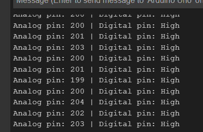
Serial.println("High");
digitalWrite (ledpin, HIGH); // if value is high,
// turn on LED & print the digital pin as "High" on the serial monitor
}
else { //otherwise
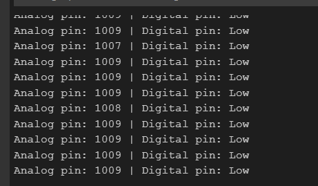
Serial.println("Low");
digitalWrite (ledpin, LOW); // LED is off and it prints digital pin as "Low" on the serial monitor
}
delay(100); // wait 100 milliSeconds
}Resources:
Sensors – Touch Sensors | element14 India
KY-036 Metal Touch Sensor Module Arduino Circuit diagram & Code (electroniclinic.com)
Leave a Reply