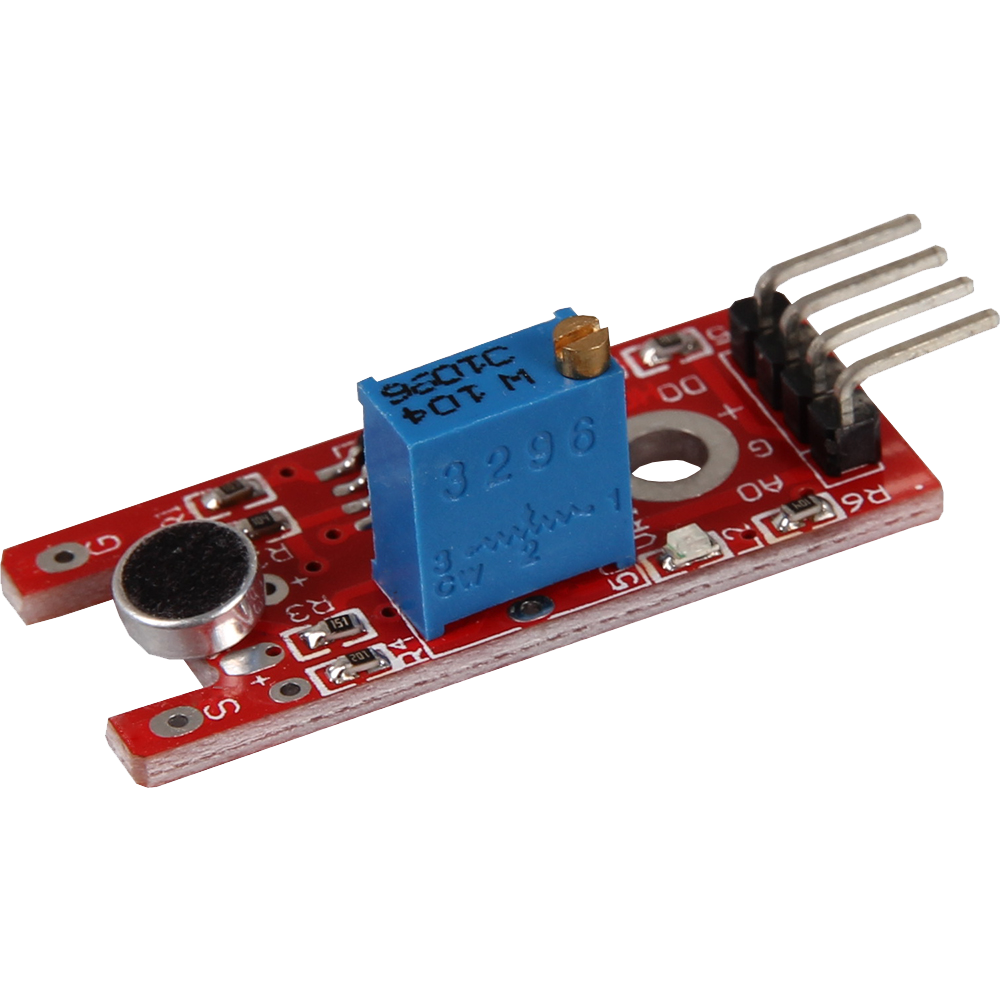
The KY-038 chip contains several component pieces of varying importance. First, the KY-038 chip comes with 4 pins: Analog output, digital output, ground, and power. The analog and digital output pins allow you to choose whether you want to work with a digital or analog signal for detecting sound. I use examples of both. The ground pin should be connected to ground on the Arduino, and the power pin should be connected to 5v on the Arduino.
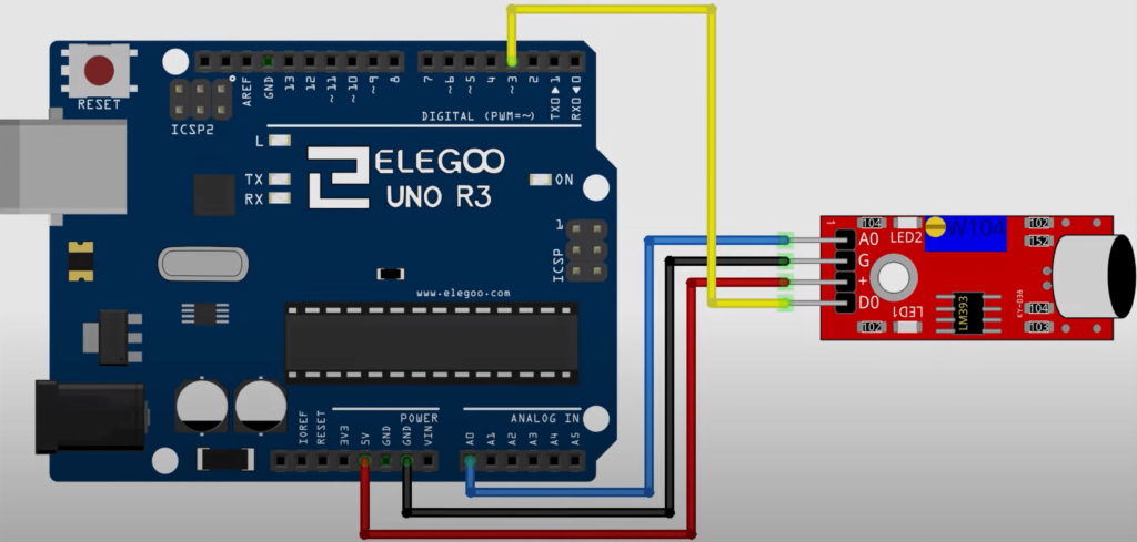
The schematic above depicts the analog out on the sensor connected to the analog in A0 pin on the Arduino. Ground on the sensor is connected to ground on the Arduino. Digital is connected to D3 on the Arduino in this example and in the code, but any digital pin would work. Power on the sensor is connected to 5v on the Arduino.
In addition to the pins, the chip also contains two LEDs. LED1 lights up whenever the chip is powered, and LED2 is used as an output. I can’t post my video here since it’s larger than the maximum file size for this site, but you can watch videos of LED2 lighting up as a sound is played.
The final major component of the chip is the Potentiometer. The potentiometer is the large, blue box on the chip with the small, gold screw on top. The potentiometer is used to adjust the sensitivity of the chip. When using the chip for the first time, You will almost certainly have to adjust the potentiometer counterclockwise until LED2 turns off during silence. Once you adjust the potentiometer to the exact point where LED2 turns off during silence, you will be golden. You can turn the screw easily using your fingernails if you have no tools on hand.
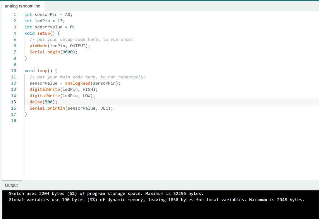
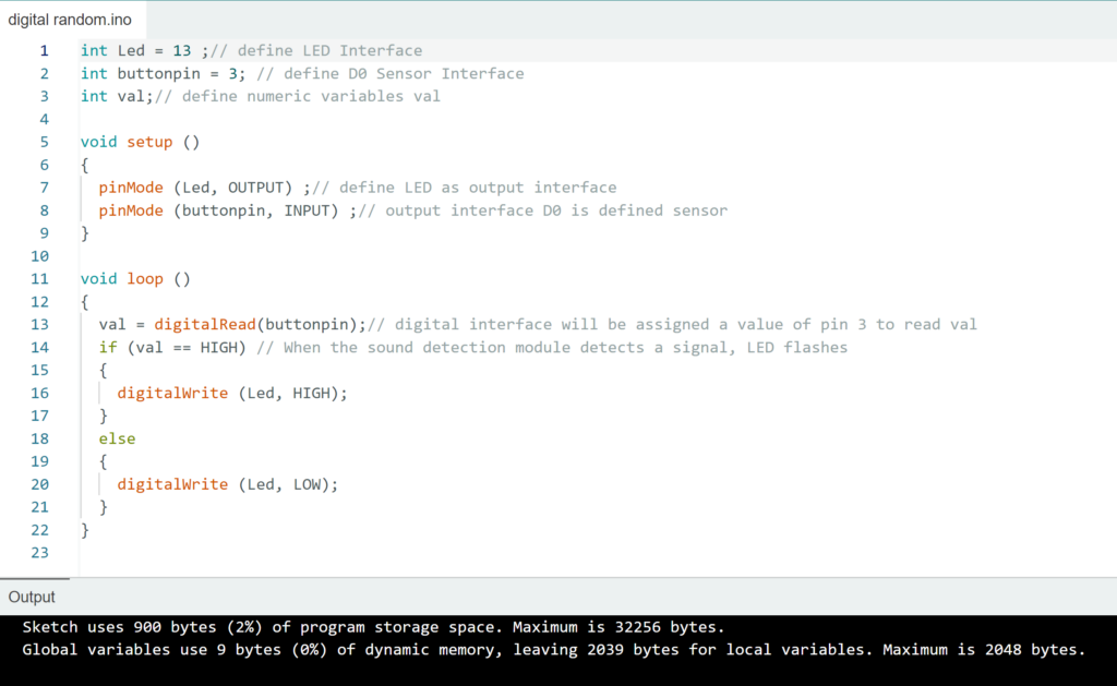
The analog output code utilizes the serial output to print values to the console. I’m not exactly sure what units of measurement the outputted values were in, probably decibels, but the values did increase as the sound got louder in my testing. As for the digital output code, it only reads whether there is sound or not and turns the LED on if there is sound and off if there’s no sound. This code could easily be given new functionality just by changing the if statements inside the loop function to do something else if sound is detected.
Notes
One thing to consider when using this sensor is that, like all other microphones, this chip works by detecting a change in pressure that moves a membrane in the microphone. This means that you can smack the microphone on the sensor and it will detect a “sound”. This also means that the chip will not work in a vacuum, if you wanted to use it there.
Another note is that there seem to be several variations of this same chip that just have different microphones. I’m not sure exactly of the differences between the microphones, or how many total variations exist, but I just know that they all should have similar functionality.
Additional Resources
Some youtube videos that helped me to understand this sensor are linked below:
Leave a Reply