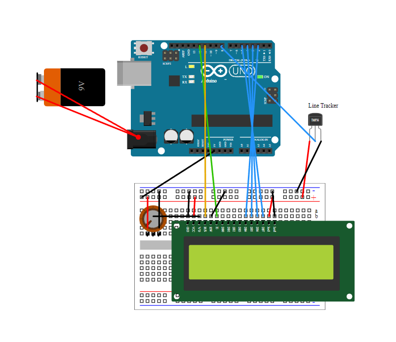
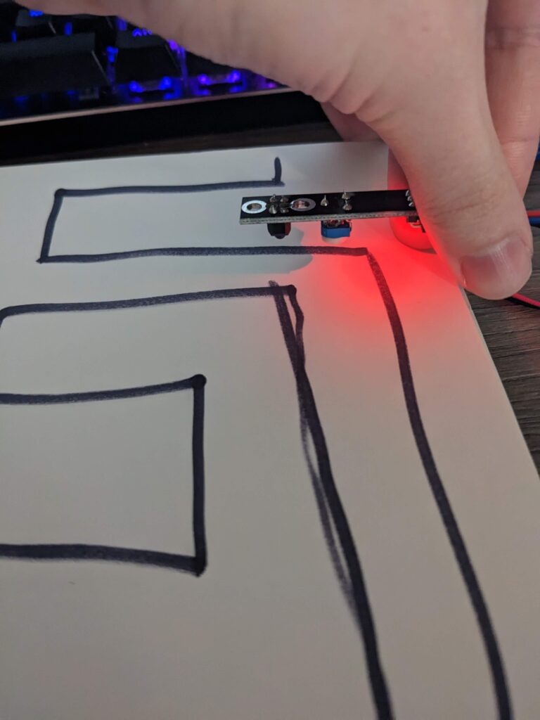
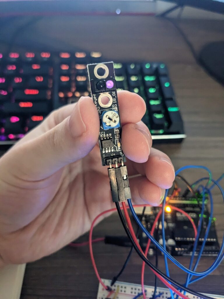
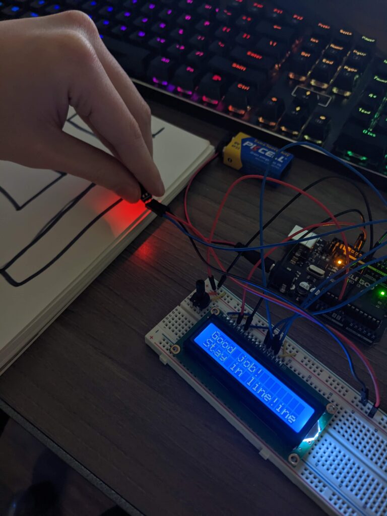
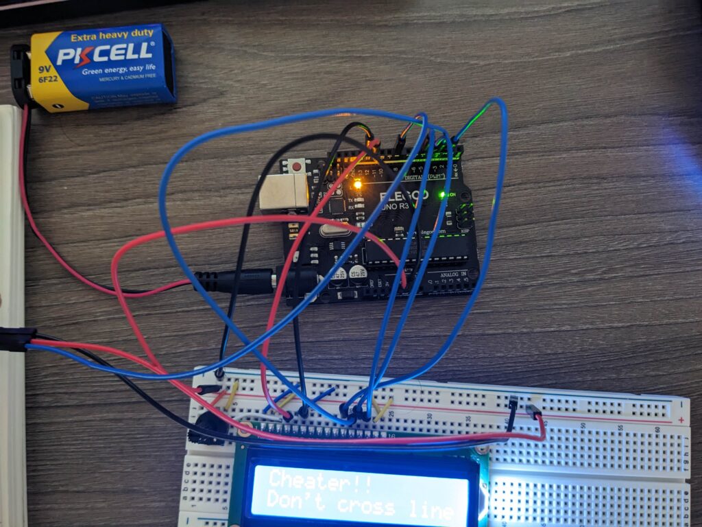
This sensor shoots out a light which tracks how much is reflected back to the source. Depending on how much of the light is reflected back determines what reading the sensor gives back. It then transmits the data back to the Arduino in the form of HIGH or LOW. HIGH indicates that the original data is not being reflected back to the source. This translates to the sensor indicating LOW whenever it is on a black line and HIGH whenever it deviates from that line. The sensor can be calibrated to see a white line on black surface or a black line on a white surface. It has to be these extremes though. Along with this the potentiometer on the sensor can be adjusted in order to change the sensitivity of the sensor. This sensor is often used in robots to help it follow a line. As this is a single sensor it’s accuracy is far below what would be required for such a task. The wiring for the device is relatively simple as it is just a digital output. This leads to the sensor only having three connecting wires, one for power, ground, and the output.
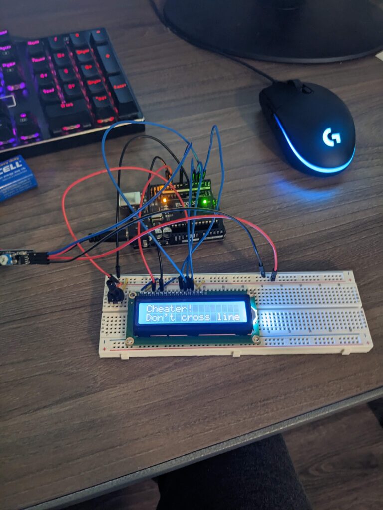
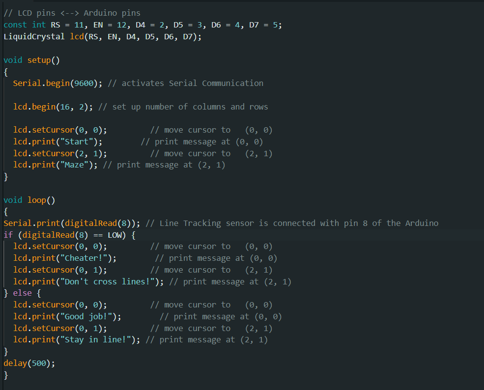
My setup takes in the reading from the sensor and changes the text on my LCD screen accordingly. This is done by reading the digital output and making use of a simple if-else block which is set on a half second delay to allow for relatively accurate tracking of the sensor’s data. One thing I did find particularly interesting was that the IDE for Arduino takes LOW or HIGH as an argument in an if-else statement and automatically translates the input in accordance with this statement. Finding documentation on this sensor was relatively difficult as it doesn’t seem to be all that popular in the Arduino space. What sites I did find often had slight differences to my model. I ended up finding a reliable source and based most of my knowledge of this sensor on that.
Sources:
https://arduinogetstarted.com/tutorials/arduino-lcd
Leave a Reply