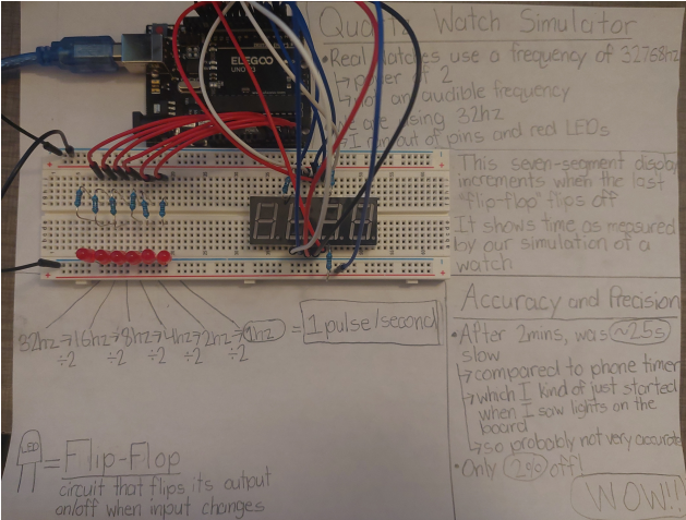
This project is a “simulation” of a quartz watch that explains the mechanism by which they work. A quartz watch uses a piezoelectric quartz crystal which pulses electricity at an exact frequency, typically 32768 hz (pulses/second.)
Our version has a frequency of 32 hz due to limitations of the number of pins and LEDs. Each red LED represents a circuit known as a flip-flop which toggles its output between on and off when it receives an input. When the flip-flop flips off, it sends a pulse to the next flip-flop in the line. By chaining them together, it is possible to effectively divide a frequency by 2 multiple times. With enough divisions, the high-hertz frequency can be changed into a frequency of 1 hz and that once-per-second pulse can be used to drive
an electric or mechanical watch.
Documentation
Date: ???
“The goal here is to create a fake chain of flip-flops using code. We don’t use the clock speed of the processor itself because of various reasons, but instead use the number of flip flops to define the time between pulses which is our “””clock speed””” so that the last flip-flop flips every 1s. This isn’t exactly accurate but I predict it will be good enough for this project”
– Travis, writing via a block comment in code at some point in the past while
sketching out the early ideas during class
Date: ???

Microsoft Paint sketch done during one of our online class meetings… sorry professor, I got distracted thinking about this. flip was my first attempt at figuring out the logic to simulate actual flip-flop circuits. Surprisingly, the final code is barely any different! setPins also mostly worked, though I did have to change it to use analogWrite rather than digital since I needed to use many pin slots for my digit display.
Date: 25 January
Current plan is to figure out a stepper motor to turn some sort of “watch hand” (piece of cardboard or something) each second. Might use the LCD display instead if the stepper motor proves to be a pain.
Date: 28 January
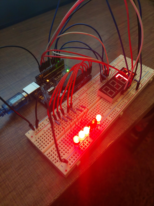
First time actually hooking up the circuitry and testing the code. Code mostly worked perfectly, circuitry was fairly smooth to assemble as well. I mean it’s basically just plugging in an LED 6 times (I’ve decided to go with 6 flip-flops since I have 6 LEDs of each color in the kit.)
Update: I saw the segmented display in the kit and decided to go with that instead of the stepper motor on impulse. Found a tutorial online:
https://www.instructables.com/Using-a-4-digit-7-segment-display-with-arduino/
It’s a little rough but I managed to follow along and plug everything in. Miraculously, it worked. Like literally, it just immediately worked with no issues. Incredible. Only issue was having to move my flip-flop signal lines down to the analog pins to make space so had to rewrite some code to adjust for that, but wasn’t a big deal.
Update: I let it run for 2 minutes and used my phone timer to compare. The display was ~2.5s slow after the 2 minutes, which is about 2% off. Not bad at all!
Code
#include "SevSeg.h"

#define NUMBER_OF_FLIP_FLOPS 6
#define FIRST_PIN 14

int flipFlops[NUMBER_OF_FLIP_FLOPS];
float timeOfLastFlip;
const int TIME_BETWEEN_FLIPS = 1000 / pow(2, NUMBER_OF_FLIP_FLOPS);

int secondsElapsed = 0;
SevSeg sevseg;

void setupSevSeg() {
    byte numDigits = 4;
    byte digitPins[] = {2, 3, 4, 5};
    byte segmentPins[] = {6, 7, 8, 9, 10, 11, 12, 13};
    bool resistorsOnSegments = 0;
    sevseg.begin(COMMON_CATHODE, numDigits, digitPins, segmentPins, resistorsOnSegments);
    sevseg.setBrightness(90);
}

void setup() {
    for (int i = 0; i < NUMBER_OF_FLIP_FLOPS; i++) {
        pinMode(FIRST_PIN + 1, OUTPUT);
    }
    setupSevSeg();
}

void loop() {
    if (millis() > timeOfLastFlip + TIME_BETWEEN_FLIPS) {
        timeOfLastFlip = millis();
        flip(0);
        setPins();
    }
    sevseg.setNumber(secondsElapsed, -1);
    sevseg.refreshDisplay();
}

void flip(int pos) {
    if (flipFlops[pos] == 0) {
        flipFlops[pos] = 1;
    } else {
        flipFlops[pos] = 0;
        if (pos + 1 < NUMBER_OF_FLIP_FLOPS) {
            flip(pos + 1);
        } else {
            secondsElapsed++;
        }
    }
}

void setPins() {
    for (int i = 0; i < NUMBER_OF_FLIP_FLOPS; i++) {
        analogWrite(FIRST_PIN + i, flipFlops[i] * 255);
    }
}
Images


Leave a Reply