by Victoria Nguyen, Jason Yang, Roger Lee
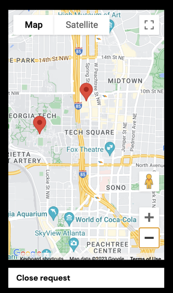
Sometimes we walk home without an umbrella. Our only option then is to walk out in the rain. But with our system, you can request an umbrella to be delivered to your general location. Someone gets to help another in need and you get to walk home dry. This becomes a fun and useful way for personal interactions. And the LED displays allow for a flashy and interesting look for the user of the umbrella.
MECHANICS
- Adafruit Electret 1063
- 8 x 19 pixels WS2812B RGB 5050SMD LED strip
- 1 x 85 pixels WS2812B RGB 5050SMD LED strip
- ESP8266 Nodemcu
- NEO-6M GPS Module
- LSM303DLHC Accel + Magnetometer
- Clear Umbrella
- Wooden hexagonal platform
- Zip ties
- Electric tape
- Arduino Uno
IDEA ITERATIONS AND SKETCHES
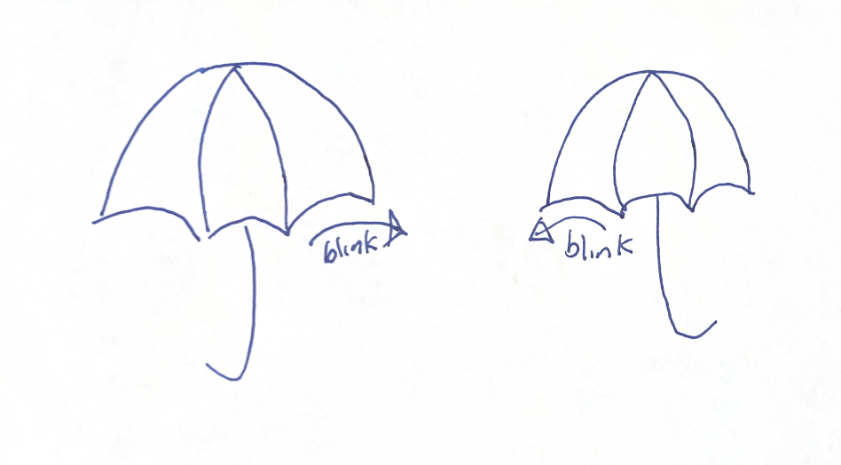
- Two umbrellas
- Our original idea was that we would make two umbrellas that could be picked up on campus. When they are picked up, they would lead to the other umbrella. This idea was meant to convey a sense of connection but the idea was thrown out due to the complication of having 2 umbrellas and because it was hard to make the connection to the environment with this idea.
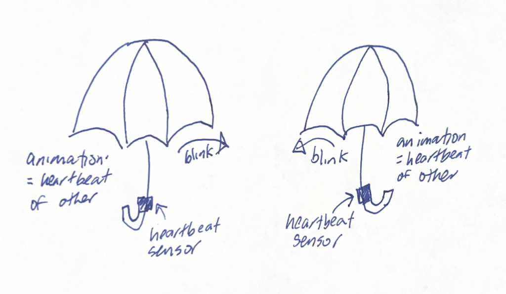
- Umbrella with heartbeat monitor
- The heartbeat monitor coincided with the two umbrella idea. An umbrella would see the heartbeat of the other umbrella and vice-versa. This idea transitioned to our current idea. We wanted the person delivering the umbrella to see the heartbeat of the requestor to convey a feeling of humanness but we had no clear way to read the heartbeat from the requester through the app. We then decided to switch who receives the heartbeat input but ran out of time to implement the idea.
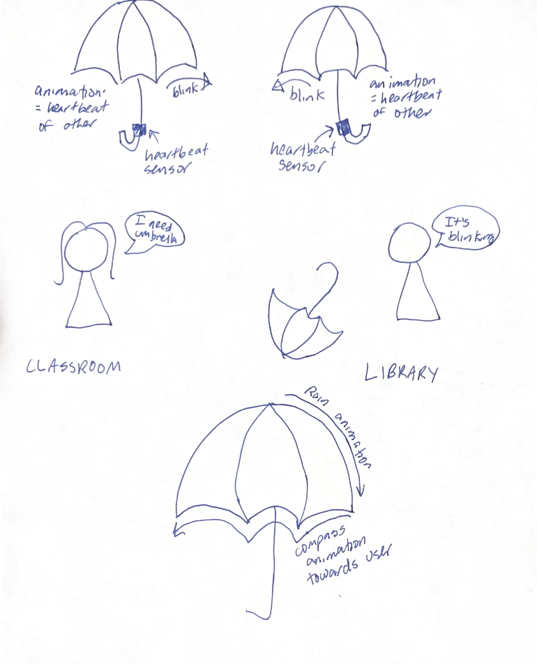
- Final idea: one compass umbrella
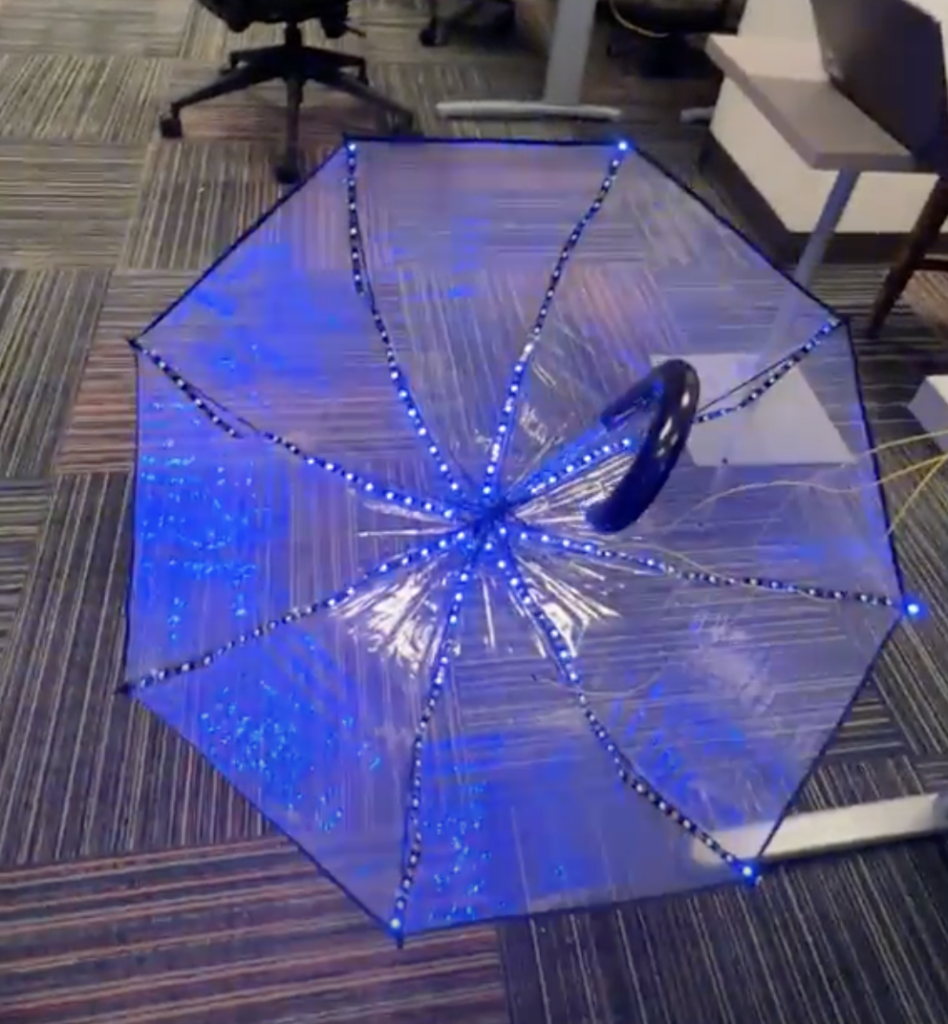
- When a user requests an umbrella, the umbrella will light up red. Once someone has picked it up, the umbrella will start to blink in the direction of the other person. Depending on how strong the rain is, there are three different rain animations.
SCHEMATICS
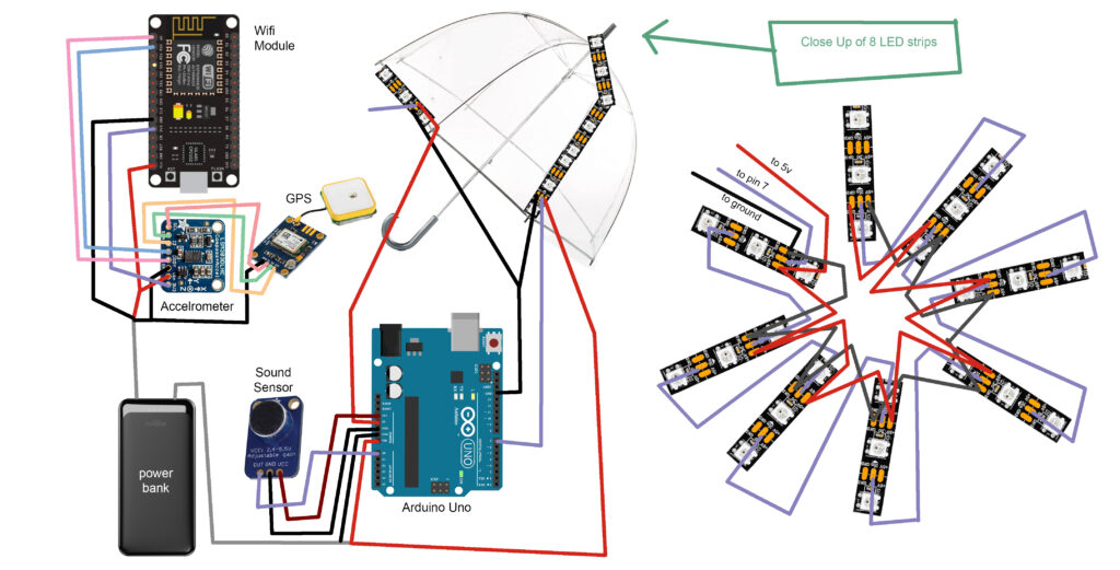
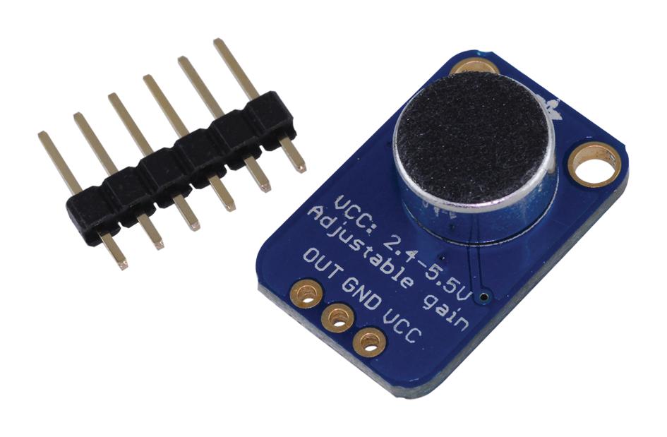
SOUND SENSOR
The sound sensor we used was the Adafruit Electret 1063. It is a microphone amplifier that senses sound and returns an analog output. Our code takes this input multiple times in 5 intervals and logs the highest and lowest inputs. This information is used to determine peak-to-peak amplitude to properly measure voltage. That value is read as a voltage by the rest of the code to differentiate different levels of sound. If the value is above certain thresholds, the umbrella’s LED patterns will play at different speeds.
WIFI MODULE
- We use an ESP8266 Nodemcu integrated board to power the GPS module, Compass module, as well as control the LED’s around the rim. The ESP8266 is used to connect to a Firebase hosted Realtime database which allows us to store the umbrella’s live latitude and longitude coordinates connected by the GPS module. We send our updated position every 4 seconds to avoid overloading the database and going above our free plan limit.
- https://www.instructables.com/IoT-ESP8266-Series-1-Connect-to-WIFI-Router/

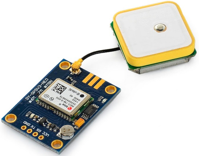
GPS MODULE
- The GPS module we use is the NEO-6M. This module allows us to connect to a satellite to obtain the longitude and latitude position of the umbrella. We send this data to the Nodemcu using software serial, and then use a Firebase ESP8266 library to send the coordinates to our real time database.
- https://randomnerdtutorials.com/guide-to-neo-6m-gps-module-with-arduino/
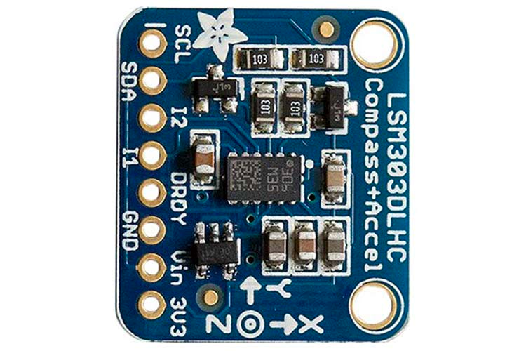
MAGNETOMETER AND ACCELEROMETER
- The magnetometer and accelerometer we use is the LSM303DLHC. It’s used for two purposes. We use the accelerometer as a tilt sensor to detect if the umbrella is on the ground or if it’s facing up. We use this to activate our compass related code when we detect if the user is moving. Otherwise, we show a red ring with the LED’s when a request has been made. We use the magnetometer to orient the umbrella to the north. Then we adjust the heading by calculating an angle between the umbrella’s position and the user’s position on the app. We add that angle to north to get our adjusted bearing which is what points the rim of lights in the direction towards the user.
- https://learn.adafruit.com/lsm303-accelerometer-slash-compass-breakout/coding
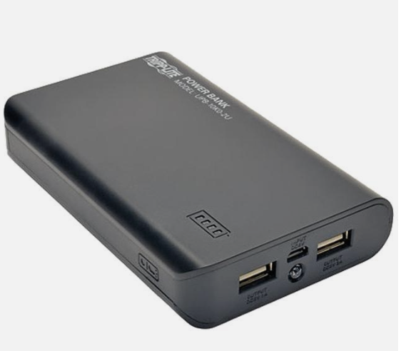
POWER BANKS
- To power our umbrella, we used a portable power bank that outputs 8-12V. Originally, we had two 5V power banks, but they were not able to power all of the components. Because we needed to power the arduino, sound sensor, wifi module, and two LED strips, we had to create a splitter to divide the current. The splitter powers the arduino through the VIN pin and powers one of the LED strips directly. The 3.3V pin on the arduino is used for the sound sensor, and the other 5V pin powers the rim LEDs. Because the arduino only has 3 ground pins, we had to create another splitter so that all four components were grounded.
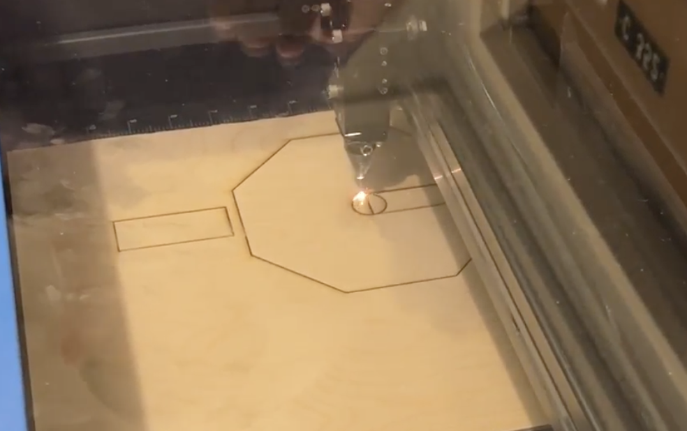
- Because our metal poles conduct electricity, we had to create a mount out of a non-conductive material. We laser cut wood into an octagon, and spray painted it.
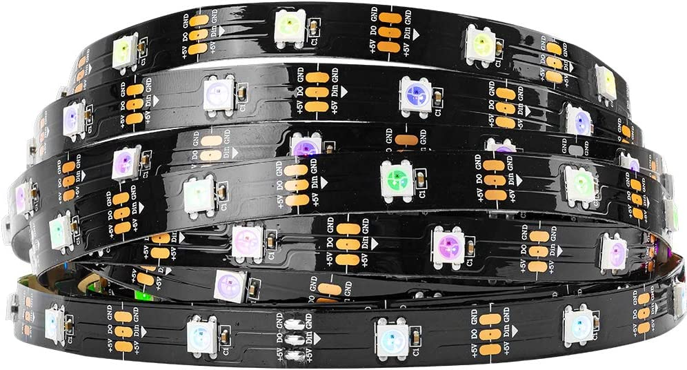
LEDS
- For the led strips, we used the WS2812B RGB 5050SMD Neopixel strips. We had 19 LEDs on each spoke of the umbrella and 85 LEDs on the rim of the umbrella. The LEDs on the spokes are connected together from the center of the umbrella layout and are controlled using the same digital output pin. The output is influenced by the sound sensor through the code. Higher detections of sound result in faster light animations. The animations light up the first LED on each spoke at the same time and then the next one until all of the LEDs on each individual spoke, are lit up. The strip on the rim is controlled using a digital output pin from the module containing the wifi and gps components. When a request is detected, the rim turns red until someone picks it up. When the umbrella is picked up, the umbrella is in compass mode and uses a green led to show which direction the user goes. The led indicator gets bigger until it lights up almost all of the LEDs on the umbrella.
SOLDERING
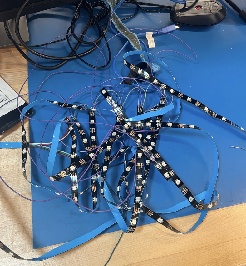
- LEDS
- To solder our rain animation LEDs, we had to connect all the power and ground inputs so that they rain concurrently. For the digital input, we had to solder the connections going through each LED strip. Each wire runs through the direction of the led strip and then to the next led strip.
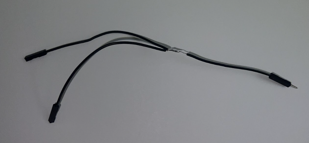
- Splitters
- We had to create splitters for power and ground
- Header pins for wifi module
- The wifi module needed to be connected to wires, so we soldered header pins onto the module and attached it using female-to-male connectors
CONSTRUCTION
The base for our product was the umbrella and wood mount. The led strips were secured to the spokes using zip ties and electric tape while all electronic components were secured to the mount using electric tape alone. The power bank was hefty and attached to the pole of the umbrella using a series of zip ties. A large amount was used to fully secure the heavy piece.
APP
- NextJS + Google Map API + Geolocation API
- The frontend of the app is built with NextJS, a react framework for web as well as the Google Map API which we use to display both the umbrella and user’s position. We also use the Geolocation web API in order to get the user’s position and then send that data to our backend.
- NextJS: https://nextjs.org/
- Geolocation API: https://developer.mozilla.org/en-US/docs/Web/API/Geolocation_API/Using_the_Geolocation_API
- Google Map API: https://developers.google.com/maps
- Firebase RTB
- The backend is built with Firebase’s realtime database, which opens a websocket that will send updated snapshots of the database whenever it changes. This lets us receive up to date positions from the umbrella in real time.
- Firebase RTB: https://firebase.google.com/docs/database
RAIN ANIMATIONS
The LEDs are controlled by setting the color of each individual pixel. To light up all the pixels, we need to create a loop that loops through each pixel and sets their color to light them up. This is the same when we want to forcibly turn off the lights of the strips. The way we connected our strips made it so that each spoke lights up after the previous one. Our library only allows us to control one strip so we had to do it that way. If we want to light up the first led on the first spoke and the second spoke at the same time, then we need to light up pixel 0 and pixel 19 in one iteration of a loop. This works the same for all other spokes. So for our loop, we incremented until the value of the number of total led strips divided by the number of spokes (152/8). This meant that to program another spoke, we add 19 to reach it. So our code loops through with this pattern and adds a delay based on the intensity of the sound.
COMPASS ANIMATION
For the compass, once we have computed the correct heading + bearing value, we just map that value to a pixel value based on how many pixels we have on the umbrella rim and divide that from 360 degrees. We also have implemented a distance based proximity, where more pixels will be lit up when the user is closer to the umbrella. This is because as the gps locations become closer, the general accuracy is a bit lower.
ISSUES
- Power
- Because of the number of LEDs and other components, we needed a lot of power to power our umbrella. We ended up using a heavy-duty power bank that gives 8 – 12 volts. Our original plan had us use 2 5volt power banks but the power draw was too low. We also had to power some of the LEDs separately from the Arduino so we had to create a power splitter and a ground splitter.
- Gps module takes awhile to connect, can range from 20s – 10 min. You must have a relatively straight line of sight to the open sky.
FINAL VIDEO
Leave a Reply