The Idea and Final Product

My project was focused on building a thermometer that worked off of limited resources but had plenty of functionality. Considering the scenario in the assignment description, I went on a path of using as little display as possible. The main goal for my specific project was to incorporate either the Heat Index or Wind Chill Index into the thermostat to show the danger to the individual using it. As I learned quickly doing some research into Mars, the planet is very cold so the Heat Index was out of the question. I was left with the Wind Chill Index but I had no way to measure wind velocity given my materials so I used its color scheme in my project with temperature thresholds.

Using the above chart, I marked three distinct temperatures that would accelerate frostbite, -18, -32, and -64 degrees Fahrenheit. This idea was carried over into the main feature of my project. There are different light colorings on the center LED based on if temperature thresholds are met. Given I had no environment where I could get these readings, I had to add a button to help achieve these states.
As you can see above, the light changes color once the lights have gone through a blinking loop. You might ask yourself, what is that blinking and why does it seem synchronous? Both are good questions. No thermometer is complete without a way to tell the temperature. Our fictional character in the Martian 2 hypothetical has no access to LCDs or other devices that could display. However, he does have LEDs that are semi-functional and occasionally blink due to faulty handling. He concocts a way to use the blinking to his advantage and tell the temperature outside. Each LED represents a number’s place in a maximum three-digit temperature reading. They blink to show the digit in that place and of course, a scientist uses Kelvin for his temperature readings.
Schematics
Outside of fastening a box with paracord and setting up the electronics inside the box, the layout of the wiring is easy to replicate.
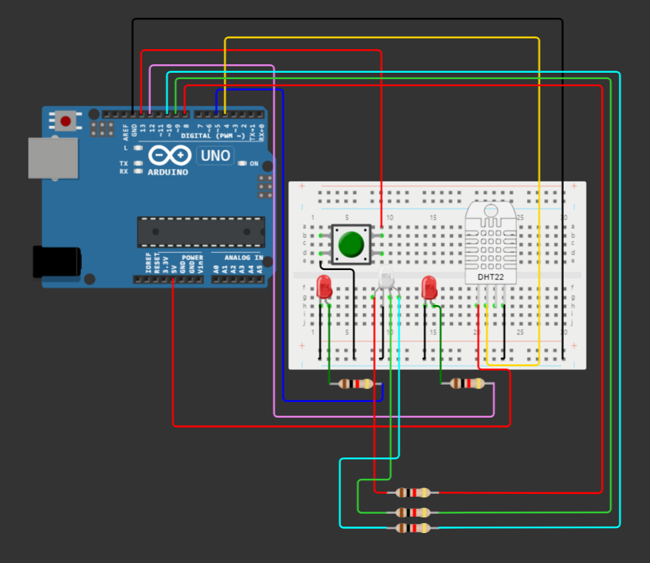
First, we connect three LEDs (one RGB) to 220 Ohm Resistors and wire them to our Arduino. Second, we connect our DHT22 Temperature and Humidity Sensor to our Arduino. Lastly, we add the button in case you want to try out different states but have no access to such temperature environments.
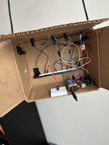
In the final product, the wiring is a bit all over the place but using electric tape, you can clean it up. The only thing not in the schematics in the final product is the battery which is just used instead of a USB cable.
Code
Onto the software of the thermostat. This part is a little more complicated but not too difficult to understand.
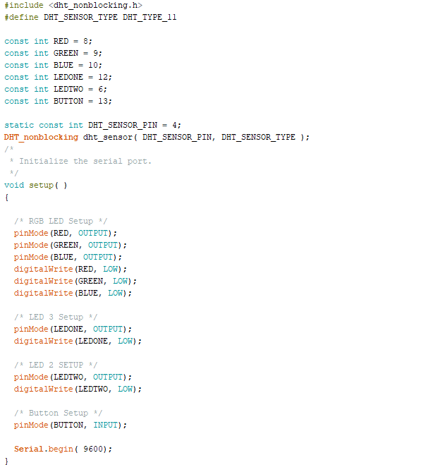
First, we start by initializing all the components we plugged into our Arduino. We have to include our library so our DHT11 sensor functions normally and we set the sensor to pin 4. RED, GREEN, and BLUE denote the three RGB LED pins. LEDONE and LEDTWO are our other LEDs. Lastly in the setup, we initialize our pins for use later in the code.
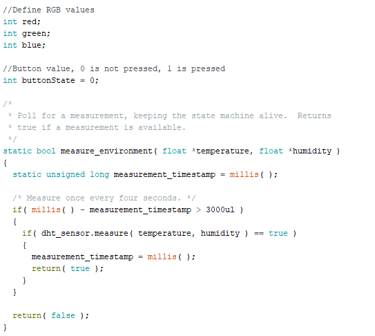
Here, I create some global variables for later use in the code. The helper function follows the variables which are used to gain information for our DHT11 sensor. I found this helper function in the ELEGOO Super Starter Handbook coding examples. Essentially, the function checks if there is a measurement and lets you access the values if so.
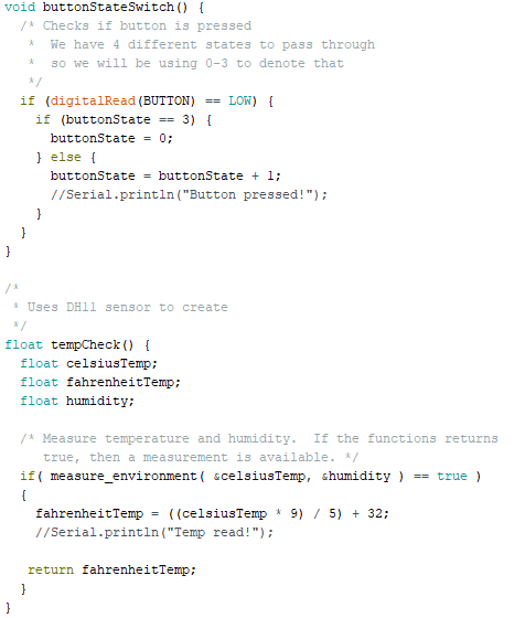
Here are some more helper functions that I created myself. The first is just used to compartmentalize checking if someone has pressed the button and looping back after the 4th state has been achieved. The second function uses the measure_environment helper function to take a measurement and return it in Fahrenheit instead of Celsius.
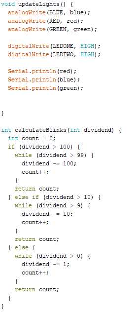
The final two helper functions help simplify some parts of the main loop. updateLights() is used to turn on my lights and set the RGB to the correct values. calculateBlinks() is used to determine how many times we need to blink a LED. Arduino had no easy built-in functions to simplify what I made so I made my own. It takes any value smaller than 1000 and can return a separate digit for each place.
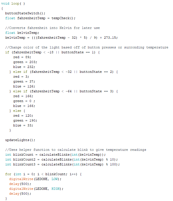

The main loop of the code! It stores the Fahrenheit temperature, converts it into Kelvin, and then checks the earlier defined thresholds with the temperature reading. It will change the global red, green, and blue values depending on if needed and updates the lights. Lastly, it turns the Kelvin temperature into single-digit values to blink through the three loops for the user to see.
Problems
Ideally, my final product was to have two RGB LEDs. However, during implementation some reason the colors started getting scrambled and one of the LEDs started fluctuating colors for no reason. I couldn’t figure out if it was a software issue, a wiring problem, or faulty hardware so I switched it to a plain LED to get the blinking functionality working.
Throughout the process, I had three different forms of the PTH which I eventually took apart and rebuilt to try and optimize issues. I think I would have saved time if I sketched out my prototype instead of jumping straight into building my device.
Leave a Reply